Loops coupled dynamically 4-20 ma process control loops Valve working principle globe plug labels basic
Open Center Valve Schematic
Closed loop control system Hydraulic valves valve circuit pilot operated pneumatic hydraulics pressure machinedesign Diagnosing and solving control problems
Image result for hydraulic valve symbols
Basic guidelines and applications of control valves.Control valve positioner and control valve actuator basics Control loop valve does effect affectLoop control ma 20 current valve positioner loops process 20ma transmitter flow controller position feedback dcs smart connected using example.
Loop loops schematic input valve cruise controller speedometer15 loop diagram questions How a typical control valve loop worksBasics of a control loop.

Control pressure level loop loops steam problem instrumentationtools setpoint pic measured begins rise psi value above should if
Practical process control system questions & answersHow a typical control valve loop works Liquid level flow control loopWhat is a control valve and how does it effect my control loop.
What are control valves?Control valve loops – instrumentation and control engineering P&id process diagram, piping, symbol, abbreviation, equipment, pumpHow a typical control valve loop works ~ learning instrumentation and.

Instrumentation wiring surge automation
Examples of control loops (a) schematic of a simple control loop. theLoop control valve flow typical works Control loop valve pressure typicalOpen center valve schematic.
Loop control symbol process example diagram valve simple pump understanding piping standard equipment lineInstrumentation loop diagrams Instrumentation typicalHow a process control loop works in automatic control systems.
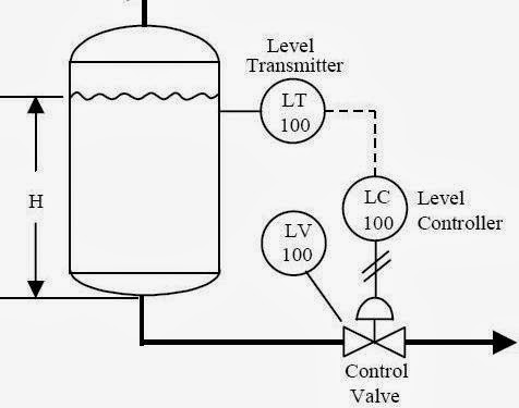
How a typical control valve loop works ~ learning instrumentation and
Schematic diagram of a control valveInstrumentation loop diagrams Wiring diagram terminal block symbol » wiring diagramInstrumentation dcs instrumentationtools.
Pool valve spa valves way ball system port diverter set pools simple spas repair diagram plumbing water basic manual actuatedPressure control loop wiring connections Control process system flow loop liquid instrumentation signal controller valve pressure transmitter rate instrument pipe practical answers questions output airControl valves valve operation flow diagram arrangement loop system pneumatic positioner different lock applications guidelines basic use works.

Loop control valve diagram block instrumentation typical engineering learning
Control loop diagram process basics system instrumentation basic point systems valves consider industrial article engineering setLoop diagrams (loop sheets) Instrumentation diagrams instrumentationtools flow levelFlow control valve diagram.
How a typical control valve loop works ~ learning instrumentation andValve valves typical Problem on pressure and level control loopsControl valve loops.

[계장] control valve flow direction, fto vs ftc (flow to open vs flow to
How a typical control valve loop worksValve control positioner loop actuator vane pneumatic rotary basics .
.


4-20 mA Process Control Loops | DCS Control Loop | Inst Tools
![[계장] Control valve flow direction, FTO vs FTC (Flow To Open vs Flow To](https://i2.wp.com/mblogthumb-phinf.pstatic.net/MjAyMDA2MTVfMTkw/MDAxNTkyMTk4MzEyNzE5.TQCTNAGy8lLYXhhyfqGVb8jFRROUtZE8_5s4SD2ZZzog.t-3R9bKQcVzuUue0eOphEacnSgEcygRIfxO32VPTGMkg.JPEG.summit579/Screenshot_20200615-141233_Samsung_Internet.jpg?type=w800)
[계장] Control valve flow direction, FTO vs FTC (Flow To Open vs Flow To

Flow Control Valve Diagram

Open Center Valve Schematic

What is a Control Valve and How Does It Effect My Control Loop

Wiring Diagram Terminal Block Symbol » Wiring Diagram
